Many Eurorack synthesizer power supplies provide not only ±12V, but also +5V power line. This is useful for digital modules, where most power is consumed by 5V or 3.3V devices. But instead of taking power directly from the +5V line, module manufacturers tend to regulate it down from +12V, overloading the +12V line unnecessarily. There are two major reasons for this:
- Backward compatibility with older and/or simpler power supplies, which do not provide +5V
- Insurance from poorly regulated 5V power supplies, which can sometimes output much larger voltage and fry the module.
The second reason was well explained by Émilie Gillet, she has also suggested to use a 5V TVS diode for protection of modules powered from a system 5V line. I’ve built on that idea and made a little adapter board that converts any +12V powered digital module into a +5V powered one.
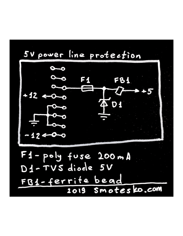 Here the TVS diode SA5.0A protects the circuit when voltage on the +5V line rises above 5V. In that case diode starts to reverse conduct and clamp the voltage down. The clamping current flows through the fuse F1, diode D1, and into the ground. When the clamping current raises above 200mA, the fuse “blows” and line becomes disconnected. F1 is a PTC “self-resetting” fuse, so it will recover when the voltage returns to the normal 5V level. Ferrite bead FB1 helps to filter down noise coming both from the system into the module, and the other way round.
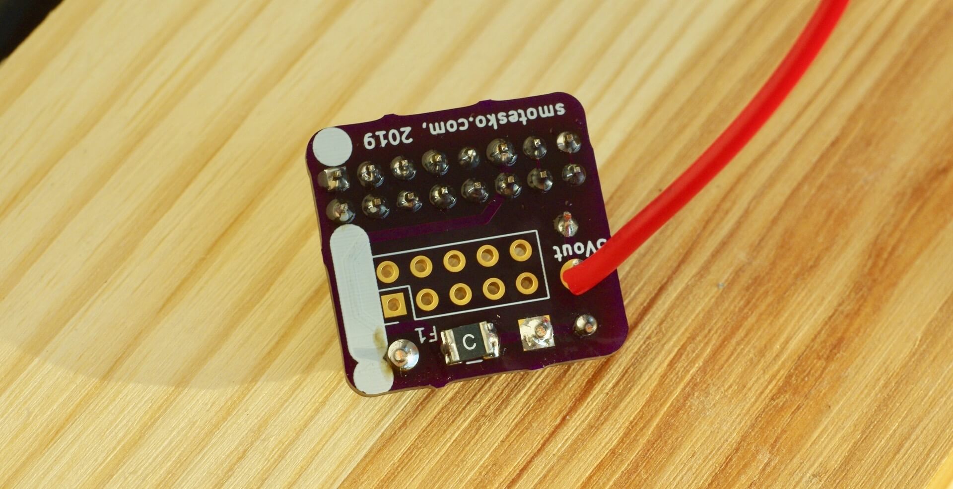
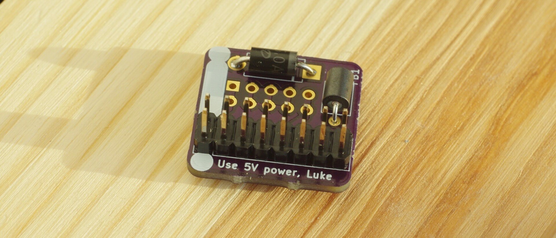 This adapter connects 2x8 system bus connector to the 2x5 module connector. On the bottom of the board there is a
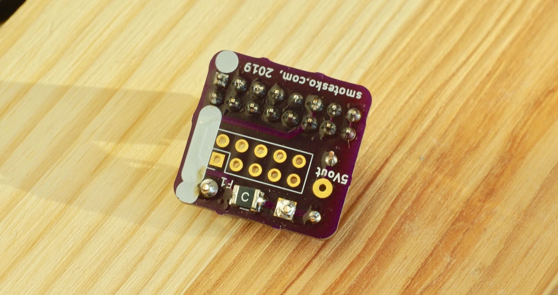
 5Vout point that should be attached to the point on a module.
 On the target module there would be a voltage regulator, usually “78L05” or “1117-5”, that has to be removed, or not ever installed when assembling a DIY module. I find the output pin of the voltage regulator and wire
 5Vout to that point.
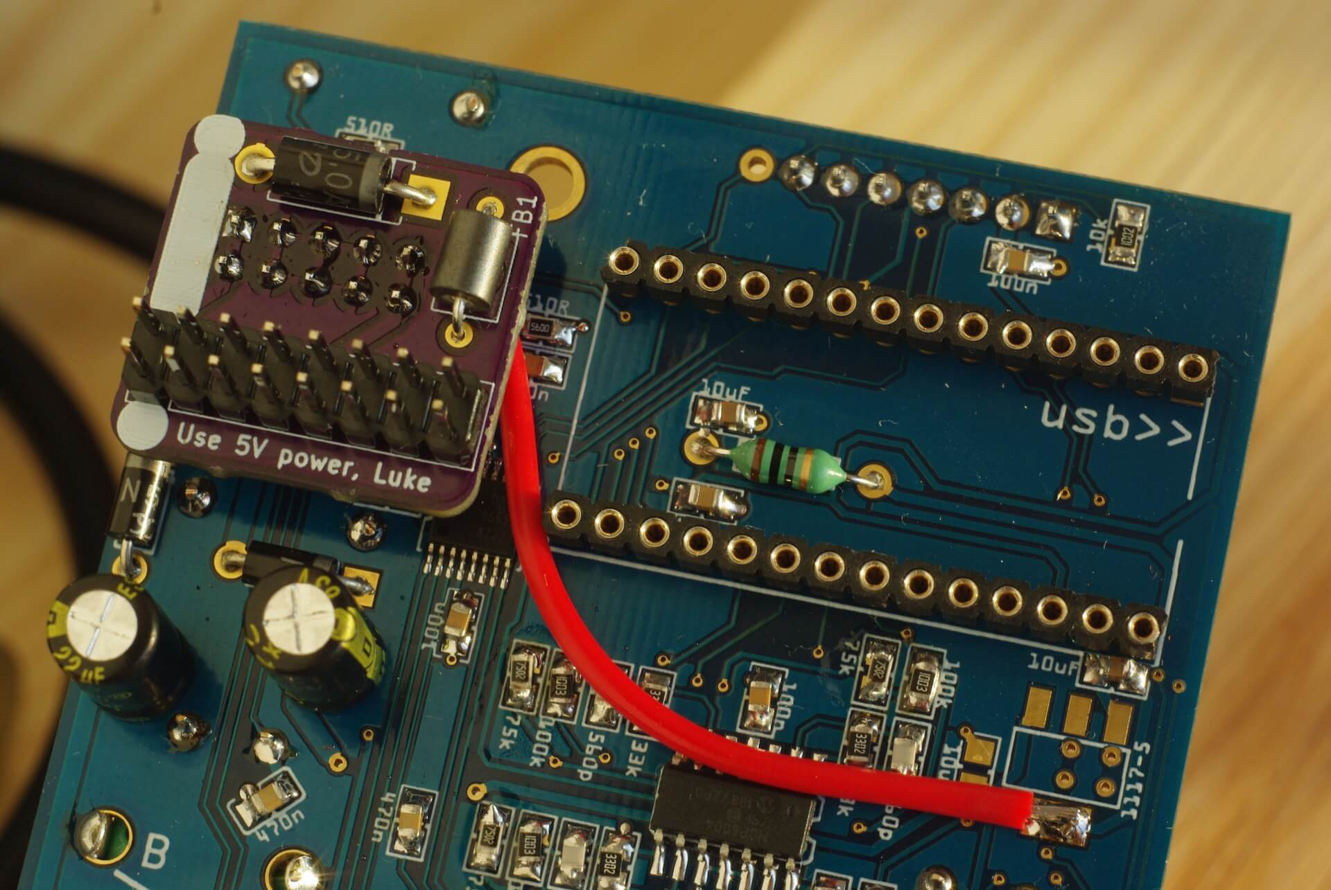
 Here is an o_C board with adapter soldered on. During assembly I skipped the 1117-5 voltage regulator and one capacitor at the input of the regulator. I did install the output capacitor. Adapter is soldered directly onto the 2x5 header and it’s a very sturdy connection without any flex.
BOM
| F1 | PTC fuse 200mA 1206 | Littlefuse 1210L020WR |
| D1 | TVS diode 5V | Vishay SA5.0A |
| FB1 | Ferrite bead | Murata BL01RN1A1F1J |
🎁 I’ve shared the board at OSHPark. You can download the kicad-pcb file or order PCBs from them.
How to find 5V injection point
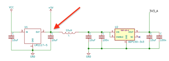
This is the section of o_C schematic where I found the point to which I should connect the 5V supply. The leftmost 10uF capacitor was not installed because it would now do nothing (almost).
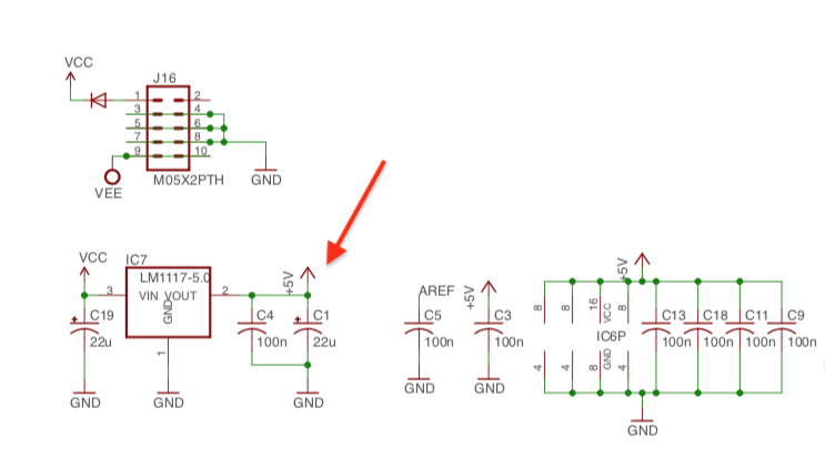
 Let’s look at another example: find the +5V point on Mutable Instruments Grids schematic. Here C19 and IC7 would be removed and wire attached to the pin 2 of IC7.