For a single row Eurorack case, I want to have a power supply that’s not too big, and can be fed from different power sources: AC-DC adapter, li-ion battery pack, car battery, USB. Unfortunately, I wasn’t able to find an easy solution for delivering 500mA on ±12V from a 5V source, so no USB this time, but for input voltages from 9 to 36 VDC this power supply should work.
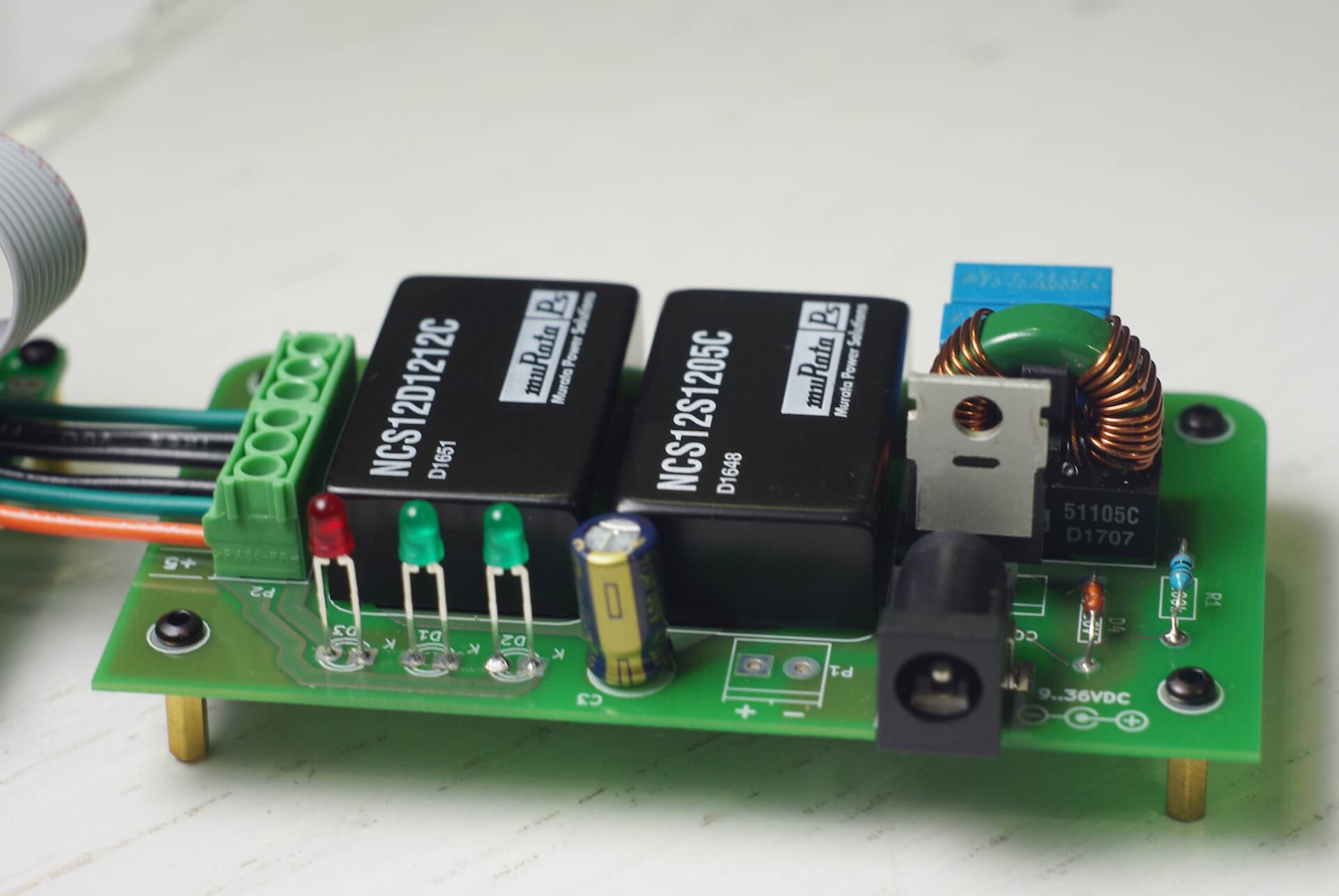
The core is two Murata NCS12 series DC-DC converter modules. They cost $30.46 each today. One delivers ±12V, the other +5V. They are isolated devices, meaning there’s no galvanic connection between input and output, even on the GND terminal. This gives protection when working with poor quality AC-DC adapters that may have insufficient isolation from mains potential. Isolation was not my initial goal, but the DC-DC converters I chose happen to be isolated, so I’ve embraced this and designed the PCB to have sufficient gap between input and output traces.
According to datasheet, max output current should be 500mA for ±12V lines and 2400mA for 5V line. This should be enough for a single row system, if most of the digital modules used would be powered from 5V line.
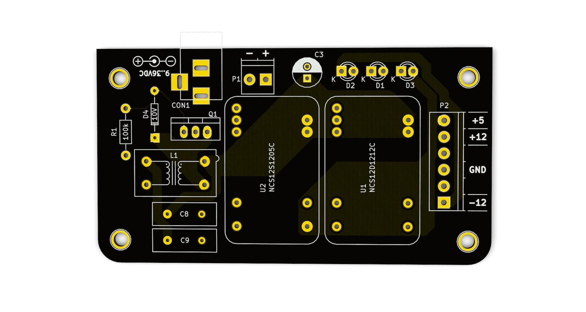
Input connector is 5.5/2.1mm barrel jack, center positive. This seems to be the most popular one. I’ve also added a screw terminal for connecting an external power input connector. If using an external connector in a metal case, the connector must be mounted on a non-conductive mounting plate, to maintain isolation between input negative voltage and system GND.
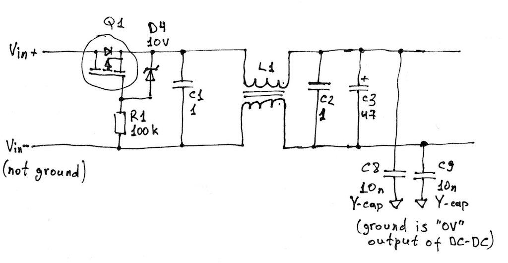
P-MOSFET transistor Q1 does reverse polarity protection on input.
Common-mode choke L1 and capacitors C8, C9 form an input and common-mode noise filter. L1 is the Murata part recommended in the NCS12 datasheet, C8 and C9 are Y-rated 250V 10nF capacitors. These components are optional. You can replace L1 with two wire jumpers and just skip C8 and C9.
C3 should be at least 50V 47uF low ESR electrolytic capacitor. All other capacitors are surface mounted on bottom side: 1uF 50V ceramics and 10uF 25V tantalums on output.
The three LED indicators connected directly to output lines are not going to melt because they are special LEDs with built-in current limiting resistors.
There are two options for mounting the PSU board. First, it can be affixed to the case back panel on four 5mm high threaded spacers. Second, it can be mounted on a panel using L-brackets. Distance from the front edge to centers of mounting holes is 6.35mm to fit Keystone 612 threaded brackets.
Full schematic PDF and KiCAD source files are published in git repo.